

Dom (17-Jan-2017):
Before heading off on a 2week trip to the (quite hot) Red Centre I was
just doing a quick sweep of my HF antenna at lunchtime. Although I have
a nice dip at 7060, it doesn’t go very low, about 1.65:1. This limits my
BW on 40m a bit. Antenna Mounted on bullbar. Any suggestions about improving the situation?
Owen (17-Jan-2017):
Terlin‘s and most taped whips have a high Q, so difficult to get to 1:1. Over time, you get a build-up of ‘road grime’ and it’s worth cleaning the male and female connectors to ensure they are not high resistance. Also, a good earth [earth strap, not cable] on the mounting arth the spring base/mount to the both the body and the chassis of the vehicle. Ensure all connectors/connections are clean.
Dom:
Hi Q
– It has a decent dip, just not low enough
Grime
– I will plan on redoing coax & connectors right through.
– I will plan on adding decent braid from bottom of mount to vehicle.
– I wont do it from spring because spring is “RF hot” on a Terlin.
Andrew (17-Jan-2017): My reply was going to be a better earth.
Dom (17-Jan-2017): currently planning on making a brass washer with tabs to sweat on 1″
braid for extra earthing to vehicle body.

Dom (17-Jan-2017):
A good thought. My experience shows that length below loading coil of antenna is not
critical – length above is extremely critical. At my work certain appropriate springs are shorted for this reason. On my vehicle is currently an old tarnished original Terlin spring, not shorted. I can try an upmarket “B” branded shorted one tonight & report back.
Owen (17-Jan-2017):
I don’t think you will be able to connect it directly to the Ae mount. If you are mounting your Ae on your bull bar, suggest mounting your earth strap on one of your bull bar mounts, where it mounts on to the Chassis. Clean away any paint where the braid will be in contact with the bull bar and smear Kopr-Kote grease between the metal surfaces to ensure good conductivity. Same with the Ae spring base, clean the metal and smear KK between the Ae base and the bull bar and Bob will be your uncle!

Ben (17-Jan-2017):
Another thought: can anyone else comment, from experience or otherwise, on the effects of the spring upon the tuning of the antenna? Pretty sure I’ve seen high quality antenna springs that have a conductor wire/braid that connects the top of the spring to the bottom, so that the flexing of the spring (which is a coil, and hence an inductor at RF) won’t affect the tuning? Is that a consideration?
Tim (17-Jan-2017): You can never have too much earthing! Rather than a washer, what I have done, is to simply “tin” the end of the braid with solder (and of course a very large soldering iron). When the solder has cooled, just drill a hole (through the braid/solder) to accept the mounting bolt.
Dom(17-Jan-2017): Not bad Tim, not bad. That’ll be my next cunning plan. I have Roger (one of the bosses ) making that weird shaped washer. It is now aluminium with two tapped M8 holes for connecting the braid. A reason I hadn’t gone with that is that solder “relaxes” & I didn’t want bolt becoming loose etc. You’ve had no problem so its back on the cards (1 outa 1 is better than VK2MB at contests). I may use that for the end that connects to vehicle body bolts. Thanks all for suggestions so far.
Horst (17-Jan-2017):
Actually, even the old cb antenna springs have braid inside… But, bear in mind that a resonant whip with a perfect ground will have a feed point impedance much less than 50 ohms. So, if you get a 1:1 swr you most likely have a poor ground.
Ben (17-Jan-2017):
For what it’s worth. What length stinger are you using? And is it mostly hanging out, or does a lot of it push into the body of the antenna? I ask as I recall some time ago that it was discovered that if a lot of stinger is pushed into the coil, it acts to detune the antenna much the same as does screwing the slug into a tuning coil in a tuned circuit. I think Tim BT discovered that a little while ago and reported back to the club one night. How about your wander lead? Is it coiled around the antenna clockwise or anti-cw? Are you using a 1:1 RF choke in the coax at all? And is the radio chassis itself earthed well to the car body? Apart from via the negative power cable conductor? Just some ideas, is all! And if a bit of impedance mismatch is the only problem, perhaps touch the ATU button on the radio (if it even has one?).
Peter (17-Jan-2017):
Both Horst and Tim’s comments are right so combining them you get this. As most of you know I used a Terlin for about 20 years. For 15 of those years it was mounted dead centre at the front of a Nissan Skyline wagon. The polyurethane coating finally started to crack and peel so it is now leaning against a wall in the shed ready to be refurbished 1 day. The spring is designed to be part of the antenna. I had the mount on a large bracket (welded up by Phil BDF) and a bonding strap to the engine block. For me that reduced internal QRM the best but I am sure every case will be different. The main issues are the different results for a resonant antenna and low SWR. They are usually not the same settings as the resonant antenna feed point impedance is not matching the feed line. Changing the antenna length to improve SWR defeats the purpose. A resonant antenna with a SWR of 2:1 at the transmitter end of the feed line is better for both TX and RX than the same antenna detuned for a perfect? SWR. Using any other form of additional matching is just wasting time, money and effort as the losses in the extra components are likely to exceed the benefits. As for the bandwidth, yes they are a bit narrow but this is due to the loading (internal coiling) and capacitance around antenna to vehicle ground and anything else ( like you standing nearby). I adjusted antenna using a GDO and observed near symmetrical change in SWR either side of resonance. I did not have to change anything until I broke the tuning stub off the top. I did use a short wire soldered to an alligator clip to lower resonance, It just hung it in the breeze on the top stub and surprisingly never detached unintentionally. The TS430 I used mobile is also up for refurbishment. Always plenty to do…
Dom (17-Jan-2017): Thanks Peter et al. My problem is with the lowest SWR, my radios protect themselves by winding back the power, so getting reduced OP as well I’m not anticipating mucking around with the stinger lengths much, just trying to lower best SWR – I suspect its indicating feed line/earthing probs which I intend to sort out this week.
Dom (19-Jan-2017):
Leaving ~Saturday Week, 28jan. I’m working on it slowly.
-I have added earth strap between Terlin base Mounting bolt & vehicle
body.
-I have renewed coax & connector through to the radio
Tim: And don’t keep us in suspense – was the SWR improved???
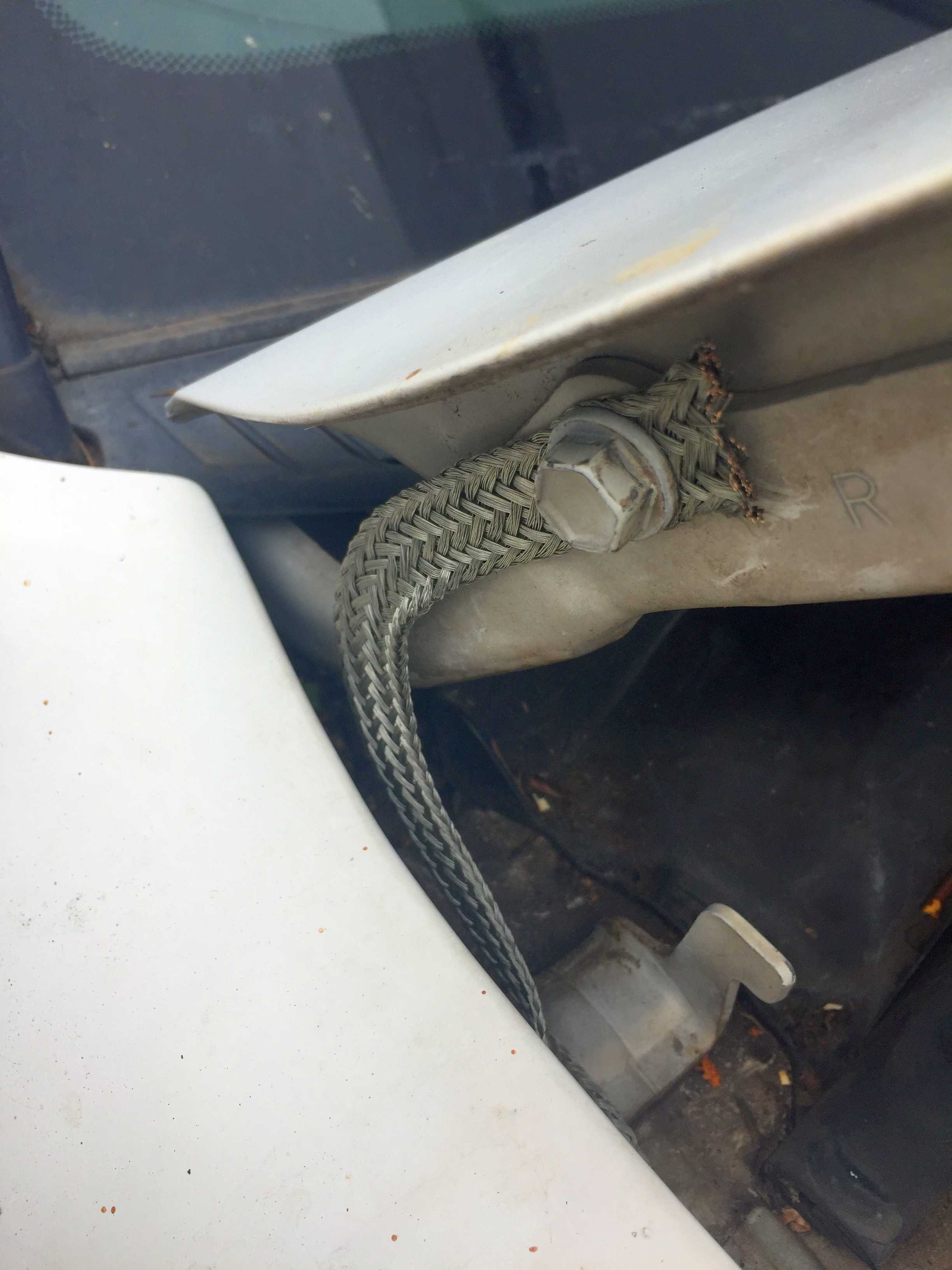

Haven’t checked SWR yet, Just spent 30min lunchtime in driveway at work adding two bonnet straps. No goo available so I’m trying it as is. Yes, I may have to redo/upgrade it later Tim 🙂
Shaun (20-Jan-2017):
This is some what of a black art for me. I installed a bracket on the tow bar, and sacrificed some 213 to get the braid to earth it. (Some times I wish I still had access to the mili ohm tester, just the 20 amp version as the 300 amp one could be problematic in a domestic
situation) because I get 0.4 ohm with or without the braid connected. And when I put the probes together I still get 0.4.On the positive side the FAMPARC antenna is 1:1 on 7.045. (Should have bough 2 of these as they not longer make them)
Dom (21-Jan-2017):
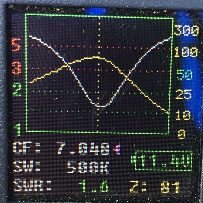
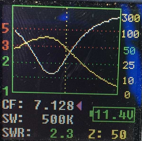
I have taken new measurements with Tim’s FG-01 after new cable/conns & earth braid – no difference.
See readings below
Lowest SWR 1,6 on 7048
Resonance on 7128
Phil (21-Jan-2017):
I am a little confused by the graphs. The antenna is essentially a Series resonant circuit that should reach the lowest impedance at resonance. It is this impedance mismatch that is giving the high VSWR. To show an impedance of 81 ohms at resonance just doesn’t seem correct. Generally the impedance of an antenna much shorter than ¼ wave is LOW, much less than 50 ohms. When the frequency is shifted either side of resonance, the impedance rises to a point where the VSWR appears lower.
Horst (21-Jan-2017):
The only reason some other antennas can produce a 1:1 swr on a well grounded mount is because they are less efficient! I have a little Tarheel which has very closely spaced turns (meaning high capacity between turns) and it produces a 1:1 swr, the big Tarheel, which is much more efficient, will not go below 2:1 unless a shunt coil is used.
Richard (21-Jan-2017):
While the FG-01 is a neat little box (I have one too), I think the impedance indicator needs to be taken with a pinch of salt. The analyser doesn’t tell you the complex impedance, i.e. a +/i jb, and I don’t recall off-hand whether that Z reading is meant to indicate the resistive component or the polar magnitude, i.e sqrt(a^2 + b^2), or something else. disclaimer: I’m a bit rusty on all this, so I could be talking complete nonsense HI).
Geoff (21-Jan-2017):
The FG-01 returns the Magnitude of a complex impedance and in a QST 2012 review it compared very well with a RigExpert and an Agilent – for resistive loads and for SWR. For complex loads it was a bit less (~90%) accurate for |Z| but was ok for SWR. Therefore, in the case of a resonant load the FG-01 “should” be accurate. It might be worth measuring the dc resistance from screw mount to top tap, say, to see what that is, in case of a fault.
I notice on the Terlin web site that all Outbacker antennas (all their antennas, in fact) are pre-tuned in the factory “to give a VSWR of < 2.0:1”.
Geoff (22-Jan-2017):
Agree with Phil’s comments you would expect to see impedance curve (even if it’s |Z|) drop to a minimum that’s below 50 ohms.. that’s your “short HF whip resonance” and then on one side of that you’d have the magic value of reactance that gives a dip in SWR. Something a bit fishy, worth having a look a bit wider in frequency and see what it’s doing elsewhere. I reckon it’s also worth seeing what a 1/4 wavelength of wire attached to the ground side does (ie a ground radial), to try and start making sense of this. Terlin may well pre-tune their part of the antenna to a decent SWR but Dom’s screwed on a different bottom half (the Cruiser) 🙂
Dom (22-Jan-2017):
Ah, but one bit of excellent news is that RF noise from the car is now almost undetectable.
It could be at S7 beforehand at different times. I suspect it was the two braids on the bonnet that have done this more than the one on the mount. This is great.
Geoff (16-Jan-2017):
In this article, W8JI reduced the impedance of his Tarheel antenna on 7MHz when he put an earth strap from the rear of his truck, where his antenna is mounted, to the main body. So I was wondering, what sort of earths you ended up with from the roo bar to your chassis. Perhaps you should have more than just the one from the Terlin base to the chassis. As Tim said, “you can never have too much earthing!”.
Screwdriver antenna (basic a centre loaded whip) with poor earth/image wswr was 2.1 or 10 db reflected is 100w forward & 10w reflected & 100Khz band pass.
Rectification/upgrade.
Install 1″ galv or braided strip bonded to base of screwdriver then to chassis + Ferrite Balun (10turns of RG174 50ohm coax) in series with coax to antenna at base + twin wire to drive motor on SD (10 turns on ferrite toriod) ex jaycar. Result:- RF shunted off coax, vswr 1.1 or -40db return loss, bandwidth 40Khz at 7095Khz as measured on Spectrum analyser. Note :- screw driver has a ferrite (red 1″ 3. – 30Mhz) toriod transformer from 50ohm to around 12ohms to match base impedance of SD antenna.
Cheers 73s
Screwdriver antenna (basic a centre loaded whip) with poor earth/image wswr was 2.1 or 10 db reflected is 100w forward & 10w reflected & 100Khz band pass.
Rectification/upgrade.
Install 1″ galv or braided strip bonded to base of screwdriver then to chassis + Ferrite Balun (10turns of RG174 50ohm coax) in series with coax to antenna at base + twin wire to drive motor on SD (10 turns on ferrite toriod) ex jaycar. Result:- RF shunted off coax, vswr 1.1 or -40db return loss, bandwidth 40Khz at 7095Khz as measured on Spectrum analyser. Note :- screw driver has a ferrite (red 1″ 3. – 30Mhz) toriod transformer from 50ohm to around 12ohms to match base impedance of SD antenna.
Cheers 73s
hi i have been reading this with interest and have wondered if you know that the
impedance on a whip will always be low around 28 ohms so to solve the issue
all you need to do is put a transformer inline 28 to 50 as found on the webb this should solve the issue
http://www.karinya.net/g3txq/cobweb/
End spacers
Now wind 8 turns of this twin cable onto a FT140-61 toroid to form a 1:1 Choke. The “crossover” winding is not an electrical requirement – it’s just an easy way to get the coaxes to emerge at opposite ends of the ferrite core. Use a couple of plastic tie-wraps to hold the coax to the core at each end.
/
Now repeat all of the above steps to form a second 1:1 Choke.
End spacers
Now bind the two 1:1 Chokes together – again, I used a couple of plastic tie-wraps. Ensure that the two Chokes are aligned – i.e. the coaxes emerge at roughly the same positions
At one end of the assembly (left side of the ‘photo) connect the coaxes in parallel: braid-to-braid, inner-to-inner; this is the end which connects to the antenna elements. At the other end of the assembly (right side of the ‘photo) connect the coaxes in series: braid from one Choke to inner of the other; this is the end which connects to the SO239 and the feedline, using the remaining braid and inner.